CAD & Mechatronics
Ball Balancing Beam
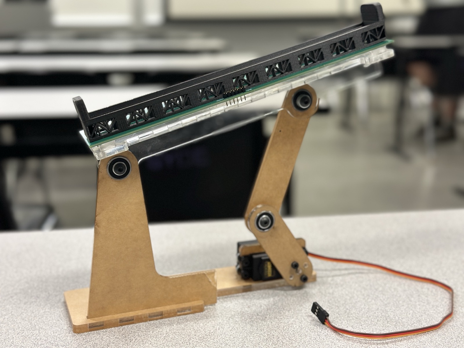
A closed-loop ball balancing beam designed in CAD and built from CNC-cut acrylic, 3D-printed parts, and a custom sensor PCB for MTE 380 at the University of Waterloo.
Overview
For MTE 380 (Fall 2026), our team of four designed and built a beam that keeps a rolling ball at a target position. I led the mechanical design, from the Onshape assembly through fabrication and assembly. A servo tilts the beam, sensors on the beam and an overhead camera report where the ball is, and a PID controller closes the loop. The mechanism had to be stiff, low-backlash, and repeatable, because any slop in the linkage shows up directly as error in the ball's position.
CAD & Mechanical Design
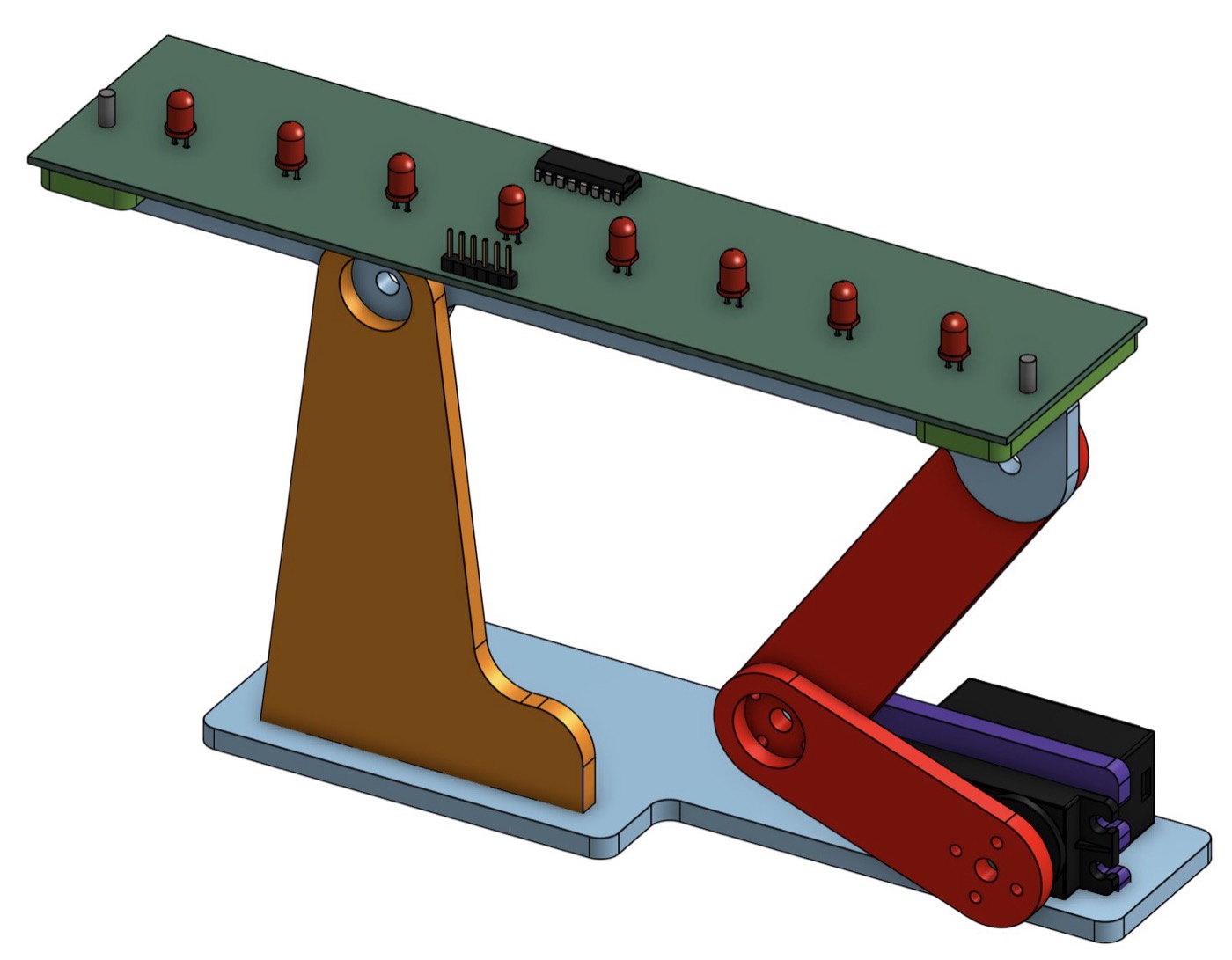
I modeled the full system as an Onshape assembly before cutting anything: frame, tower, linkage, servo, beam, and the sensor PCB with its components. Having the electronics in the assembly let me check clearances between the board, the trough, and the moving linkage across the beam's full range of travel.
- Drive: an MG995 servo turns a crank that pushes a coupler link up to the free end of the beam, forming a four-bar linkage that converts servo rotation into beam tilt
- Pivots: the beam hinges on a tapered tower at one end, with ball bearings at every joint to keep friction and backlash low
- Tower: a tapered upright with a filleted foot that keys into the base, keeping the beam pivot stiff in bending
- Beam: an acrylic beam carries the sensor PCB on 10 mm dowel standoffs, with a printed trough on top that guides the ball
- Servo mount: a cradle on the base locates the servo so its output shaft lines up with the linkage plane
Manufacturing
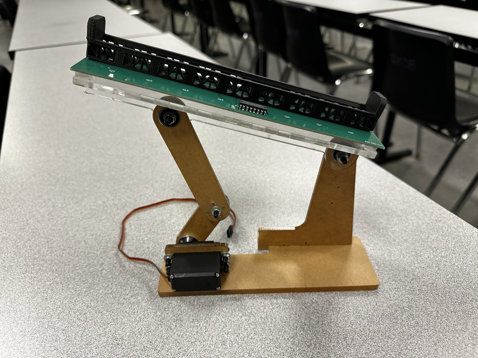
- CNC-cut the base, tower, and linkage plates from 4 mm acrylic sheet, using finger joints and slots so the parts interlock
- Kept the whole frame inside a 220 mm envelope
- Press-fit ball bearings into the tower and linkage plates, then secured each joint with screws and nuts
- 3D printed the ball trough in PLA as an open truss, which gave the phototransistors underneath a clear view of the ball while still forming a smooth channel for it to roll in, with end stops at both ends
- Mounted the sensor PCB on 10 mm dowels so the phototransistors sit just below the trough
Design Iterations
Most iterations went into tolerances and stiffness, the two things that most affected how well the controller could perform.
- Tolerances: the acrylic sheet varied in thickness across its area, so the finger joints, slots, and bearing bores that fit in one spot were loose or tight in another. I tuned the joint and press-fit clearances through cut-and-test trials until the parts assembled tight everywhere
- Stiffness: any flex or play in the frame and linkage shows up as error in the ball's position, so I iterated on the frame and joints to make the structure as sturdy as possible and minimize control error
Sensing & Control
- 8 TEPT5600 phototransistors along the beam share a single ADC pin through a 74HC4051 multiplexer
- An overhead camera tracks the ball by colour in OpenCV
- A PID controller in Python turns position error into a beam angle and sends it to an Arduino Mega over serial, which drives the servo